Before I start I want to mention that yes, I am aware of Blue Sea's ACR products. Installing involves a fair bit of rewiring on my older boat, and I was more comfortable with something that was more like the traditional Perko rotating bank selection scheme (to the point they can exist in parallel, leaving the Perko as a backup.) Rewiring to isolate the start circuit from the rest probably has some advantages... maybe next project. The same isolation is not precluded by the scheme I went with, though automating it either way requires a little bit more... that was part of my plan anyway.
Another objection, the ACR is activated by sensing voltage drop on the house bank, which means the starter load is drawn from the house bank, if only for a split second. I don't see the point of using an indirect signal like that, when a very direct one is readily available: the start wire of the key switch.
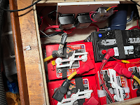
As the title suggests the heart of this plan is the Blue Sea ML Series 7701 -- a pair of them. When one of them is in the closed position the start bank is connected, when the other is closed the house bank is connected, when both are closed... do the math. They are manually controlled using the included switches, with built-in status LEDs. (The 7701 is a mechanically latching relay, it only draws power momentarily, when changing positions... beyond the minute amount used by the LEDs of course.)
As for automation, this solution doesn't rely on any microprocessors, nor any ICs of any kind, it's just simple, electro-mechanical. The core concept of it is a relay coil with a polarized capacitor and a resistor, all wired in parallel. That causes the coil to stay actuated for about 0.5 seconds after power to it is dropped. (The diodes are to prevent back-feed when the coil field collapses.)
Used in tandem with a primary relay, it sets up a momentary electrical signal, after some other signal raises and then drops. In this case, after cranking the engine (which supplies power to both relays and thus selects the start bank) the resulting momentary signal deselects the start bank, when the power to both relays is dropped, while the delayed relay remains energized. This condition is only present for a half-second.
To make sure that the start bank wasn't the only one selected when it is automatically deselected, the circuit selects the house bank (if it isn't already.) The net effect is that both banks are selected while cranking, and when done cranking, the start bank is deselected, making sure it is not accidentally forgotten/left connected to house loads.
The circuit also includes a lock-out jumper, to easily disable all automatic bank selection/deselection, if necessary.
My boat has an echo charger, that charges both banks behind the bank selection scheme, a necessary component to make deselecting the start bank after cranking, practical.
The duration of cranking is generally short enough to use as the "close" signal to the 7701 for the start bank. But it could be a problem if the engine is cranked for more than 10 seconds, in which case the 7701 locks out all signals for 30 seconds if either signal is sent continuously for more than 10 seconds. If this occurred the start bank would not be deselected, thus requiring the user to either avoid cranking for more than 10 seconds, or to wait 30 seconds before trying again. While these are both sensible practices, this device is about automating bank management.
To address this I added the same mechanism for the run signal, as an option. If the run signal is connected, it doesn't deselect the start bank until the key is turned to off. (This also makes it workable in absence of an echo charger.) It is still possible for deselect to be ignored, but for that to happen the user would have to crank more than 10 seconds, then kill the engine (if it started) and turn the key off less than 30 seconds after.
If you wanted to omit this feature, it would save a resistor (RES_RUN_DELAY), a capacitor (CAP_RUN_DELAY) and both run relays. Those components could be left off the board, but RUN_DELAY [relay] pins 6 and 7 would need to be jumpered, by adding a short piece of wire between them. (Pins 6 and 7 are denoted on the board graphic.) This would save about $8 in components. The feature can also be disabled by leaving its option jumper open, if the board is fully populated.
This is the full schematic:
Terminal block wire size range: 16 AWG to 24 AWG
Circuit Idle Power Consumption: 0 mA
Max current across board traces: 2A
All components sourced from DigiKey.com, at this moment they cost $16.48:
1 qty  |
2 qty  |
2 qty  |
2 qty  495-6061-ND B41890A5108M000 CAP ALUM 1000UF 20% 25V RADIAL |
2 qty  |
|
|
|
The relays were chosen because they are fully sealed, contact ampacity is many times Blue Sea's fuse recommendation (which itself is many times more than will ever be drawn normally) and duty specs should be easily more than adequate.
Note that unit prices change often, sometimes substantially, so I didn't include them. (It's actually cheaper to buy 10 diodes than 8, but the board only needs 8.)
I have the PCBs made by a company in China, it only costs about $4.50 for 5 of them, including shipping. So I have 3 extras, if anyone wants one, leave a comment.
Permission for personal use of this board design is hereby granted, it may not be reproduced and sold to any third party without express written consent.


Comments
Post a Comment